
GSM BASED HOME AUTOMATION USING ARDUINO AND SIM900 GSM MODULE


Bless Home is a IoT project through which we can control all the switches, lights and fans of our home through our smart phones via a application.
GSM controlled home automation systems are widely used and can be found easily on internet, but as we all know, the prices are very prohibitive for general consumers. This is why I've tried to build some sort of device based on open-source knowledge that can be replicate by all the hobbyists, even if they are amateurs or professionals.
So I begun to think what kind of basic home appliances could be remote controlled via GSM network and nothing else? We all know, that you can control lights, heating, multimedia system and so on, but I've tried to make my project closer for my basic needs: lighting and heating (optional - garage doors, but it's not my case because I live on a 3rd floor apartment).
I mention that the finished prototype, seen in the photo, can be used safely (with a bit of tweaks, of course) on any kind of building with or without garage (the garage door relay can be repurposed for any other activity).
COMPONENTS REQUIRED
- an arduino uno or any series of arduino
- SIM900 GSM SHIELD
- relay module
- active 3G sim card
- male-female jumper wires
- male-male jumper wire
- a plastic box
- a bulb
- a bulb socket
- electrical wires
- few nuts and bolts to lace bulb socket on the plastic box.
SIM800 GSM MODULE

GSM / GPRS Quad Band TTL UART Modem - SIM800, from rhydoLABZ, is built with Quad Band GSM/GPRS engine- SIM800, works on frequencies 850/ 900/ 1800/ 1900 MHz. The Modem comes with selectable interfacing voltage, which allows you to connect 5V & 3V3 microcontroller directly without any level conversion chips. The baud rate is configurable from 9600-115200 through AT command. The GSM/GPRS Modem is having internal TCP/IP stack to enable you to connect with internet via GPRS. It is suitable for SMS, Voice as well as DATA transfer application in M2M interface.
The Modem is manufactured with Automatic Pick and place machine with high quality standard. The onboard Low dropout 3A Power supply allows you to connect wide range unregulated power supply (5V-12V). Using this modem,you can make audio calls, SMS, Read SMS, attend the incoming calls and internet etc through simple AT commands.
SIM800 Modem Features:
- AT command interface
- Quad-band 850/900/1800/1900MHz
- Make and receive voice calls
- Send and receive SMS messages
- Send and receive GPRS data (TCP/IP, HTTP, etc.)
- Bluetooth connectivity
- Configurable Baud rate (9600-115200, factory default value: 9600)
- Standard Audio Jack Connectors for external speaker and mic
- Selectable interface between hardware serial port and software serial port
- Inbuilt Powerful TCP/IP protocol stack for internet data transfer over GPRS.
- SMA Connector with external antenna
- Indicator LEDs for Power, Netlight and Status
- Standard Flap type SMA Socket
- ESD Protection over TVS Zener array
- Input Voltage: 5V-12V DC
- Normal operation temperature: -20 °C to +55 °C
ONE CHANNEL RELAY MODULE

WHAT IS A RELAY?
A relay is an electrically operated device. It has a control system and (also called input circuit or input contactor) and controlled system (also called output circuit or output cont actor). It is frequently used in automatic control circuit. To put it simply, it is an automatic switch to controlling a high-current circuit with a low-current signal.
The advantages of a relay lie in its lower inertia of the moving, stability, long-term reliability and small volume. It is widely adopted in devices of power protection, automation technology, sport, remote control, reconnaissance and communication, as well as in devices of electromechanics and power electronics. Generally speaking, a relay contains an induction part which can reflect input variable like current, voltage, power, resistance, frequency, temperature, pressure, speed and light etc. It also contains an actuator module (output) which can energize or de-energize the connection of controlled circuit. There is an intermediary part between input part and output part that is used to coupling and isolate input current, as well as actuate the output. When the rated value of input (voltage, current and temperature etc.) is above the critical value, the controlled output circuit of relay will be energized or de-energized.
NB: input into a relay can be divided into two categories: electrical quantities (including current, voltage, frequency, power etc.) and non- electrical quantities(including temperature, pressure, speed, etc.)
FEATURES
- The features of 1-Channel Relay module are as follow:
- Good in safety. In power system and high voltage system, the lower current can control the higher one.
- 1-channel high voltage system output, meeting the needs of single channel control
- Wide range of controllable voltage.
- Being able to control high load current, which can reach 240V, 10A
- With a normally-open (NO) contact and a normally-closed (NC) contacts
PINS OUT
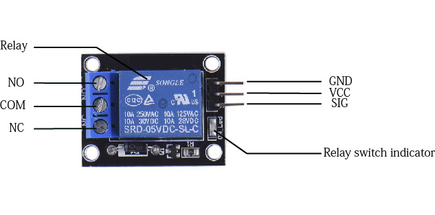
INPUT
It has a 1×3 (2.54mm pitch) pin header for connecting power (5V and 0V), and for controlling the relay. The pins are marked on the PCB:
- GND – Connect 0V to this pin.
- SIG – Controls this relay, active Low! Relay will turn on when this input goes below about 2.0V
- VCC – Connect 5V to this pin. Is used to power the opto couplers
OUTPUT
The 1 channel relay module could be considered like a series switches: 1 normally Open (NO), 1 normally closed (NC) and 1 common Pins (COM).
- COM- Common pin
- NC- Normally Closed, in which case NC is connected with COM when INT1 is set low and disconnected when INT1 is high
- NO- Normally Open, in which case NO is disconnected with COM1 when INT1 is set low and connected when INT1 is high
HOW RELAY WORKS?
The working of a relay can be better understood by explaining the following diagram given below.
There are 5 parts in every relay:
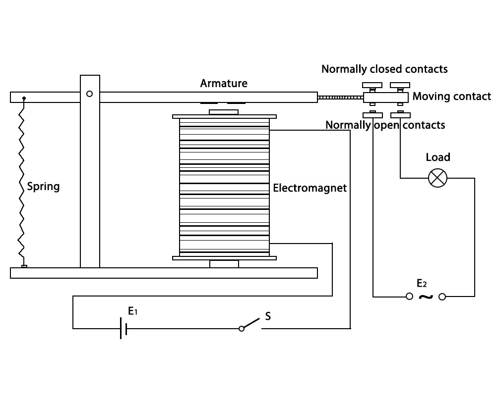
1. Electromagnet – It consists of an iron core wounded by coil of wires. When electricity is passed through, it becomes magnetic. Therefore, it is called electromagnet.
2. Armature – The movable magnetic strip is known as armature. When current flows through them, the coil is it energized thus producing a magnetic field which is used to make or break the normally open (N/O) or normally close (N/C) points. And the armature can be moved with direct current (DC) as well as alternating current (AC).
3. Spring – When no currents flow through the coil on the electromagnet, the spring pulls the armature away so the circuit cannot be completed.
4. Set of electrical contacts – There are two contact points:
.Normally open – connected when the relay is activated, and disconnected when it is inactive.
.Normally close – not connected when the relay is activated, and connected when it is inactive.
5. Molded frame – Relays are covered with plastic for protection.
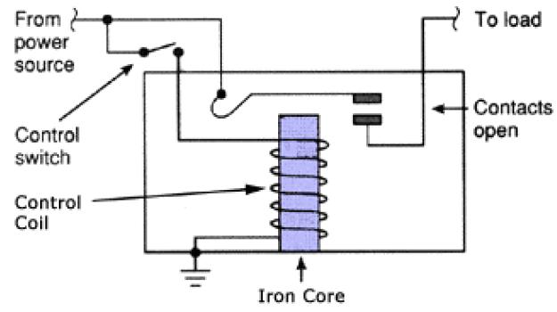
Principle
The diagram shows an inner section diagram of a relay. An iron core is surrounded by a control coil. As shown, the power source is given to the electromagnet through a control switch and through contacts to the load. When current starts flowing through the control coil, the electromagnet starts energizing and thus intensifies the magnetic field. Thus the upper contact arm starts to be attracted to the lower fixed arm and thus closes the contacts causing a short circuit for the power to the load. On the other hand, if the relay was already de-energized when the contacts were closed, then the contact move oppositely and make an open circuit.
As soon as the coil current is off, the movable armature will be returned by a force back to its initial position. This force will be almost equal to half the strength of the magnetic force. This force is mainly provided by two factors. They are the spring and also gravity.
Relays are mainly made for two basic operations. One is low voltage application and the other is high voltage. For low voltage applications, more preference will be given to reduce the noise of the whole circuit. For high voltage applications, they are mainly designed to reduce a phenomenon called arcing.
RELAY APPLICATIONS
Relays are used to protect the electrical system and to minimize the damage to the equipment connected in the system due to over currents/voltages. The relay is used for the purpose of protection of the equipment connected with it.
These are used to control the high voltage circuit with low voltage signal in applications audio amplifiers and some types of modems.
These are used to control a high current circuit by a low current signal in the applications like starter solenoid in automobile. These can detect and isolate the faults that occurred in power transmission and distribution system. Typical application areas of the relays include
- Lighting control systems
- Telecommunication
- Industrial process controllers
- Traffic control
- Motor drives control
- Protection systems of electrical power system
- Computer interfaces
- Automotive
- Home appliances


SENDING TEXT MESSAGE THROUGH PHONE AND SEE COMMAND ON SERIAL MONITOR


CIRCUIT DIAGRAM, SOURCE CODE AND REPORT
As all we know, these types of projects requires a lot of time and money to invest to get the successful result. For making more projects and for presenting more contents to my visitors, Whoopee Webs need financial support from all their visitors.
Due to the reason mentioned, the circuit diagram, source code and well maintained & prepared report of Bless Home project can be your's by spending a very small amount to Whoopee Webs, so that we can brings a lot of content for all of you guys.

![Java Project - Stock Management System [with full source code, demo video, report and documentation]](https://blogger.googleusercontent.com/img/b/R29vZ2xl/AVvXsEjkczomkD0V220aPTTTAEmpXjnEuaJbeUrPiAs0ScrkkggKmP_0XsLAQnI97TRjfF-CAZqncbEwZSkBz01Yc-KpmpSmQtVUPI3puBG2_oz4sPXPFu_QYWIMvQXWkRYxNZYH7m08IXD7C2ch/w680/1.PNG)


0 Comments